Dodge Journey: Removal
FRONT
1. Raise and support the vehicle.

Fig. 163: TIRE AND WHEEL MOUNTING
2. Remove the wheel mounting nuts (3), then the tire and wheel assembly (1).
NOTE: In some cases, it may be necessary to retract the caliper piston in its bore a small amount in order to provide sufficient clearance between the pads and the rotor to easily remove the caliper from the knuckle. This can usually be accomplished before removal by grasping the inboard side of the caliper and pulling outward working with the guide pins, thus retracting the piston. Never push on the piston directly as it may get damaged.
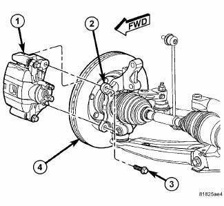
Fig. 164: CALIPER/ADAPTER MOUNTING
3. Remove the two bolts (3) securing disc brake caliper and adapter bracket (1) to the steering knuckle (2).
4. Remove the disc brake caliper and adapter bracket (1) from the knuckle (2) and rotor (4) as an assembly.
Hang the assembly out of the way using wire or a bungee cord. Use care not to overextend the brake hose when doing this.
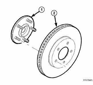
Fig. 165: VENTED BRAKE ROTOR MOUNTING
5. Remove any clips retaining the brake rotor to the wheel mounting studs.
6. Slide the brake rotor (2) off the hub and bearing (1).
REAR
1. Raise and support the vehicle.
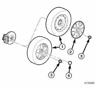
Fig. 166: TIRE AND WHEEL MOUNTING
2. Remove the wheel mounting nuts (3), then the tire and wheel assembly (1).
NOTE: In some cases, it may be necessary to retract the caliper piston in its bore a small amount in order to provide sufficient clearance between the pads and the rotor to easily remove the caliper from the knuckle. This can usually be accomplished before removal by grasping the inboard side of the caliper and pulling outward working with the guide pins, thus retracting the piston. Never push on the piston directly as it may get damaged.
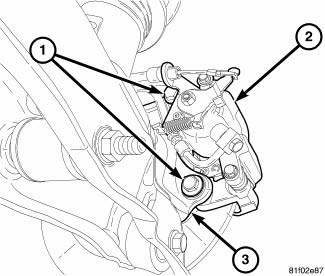
Fig. 167: REAR CALIPER ADAPTER MOUNTING
3. Remove two bolts (1) securing the disc brake caliper and adapter bracket ( 2) to the knuckle (3).
4. Remove the disc brake caliper and adapter bracket (2) as an assembly from the knuckle (3) and rotor.
Hang the assembly out of the way using wire or a bungee cord. Use care not to overextend the brake hose when doing this.
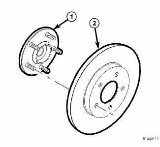
Fig. 168: SOLID BRAKE ROTOR MOUNTING
5. Remove any retaining clips, then slide the brake rotor (2) off the hub and bearing (1).
 Standard procedure
BRAKE ROTOR MACHINING
NOTE: Refacing the rotor is not required each time the brake pads are
replaced, only
when the need is foreseen.
Any servicing of the rotor requires extreme care to ma ...
 Installation
FRONT
NOTE: Inspect disc brake pads before installation.
Fig. 169: VENTED BRAKE ROTOR MOUNTING
1. Clean the hub face (1) to remove any dirt or corrosion where the rotor
mounts.
2. Insta ...
See also:
Adjustments
ADJUSTMENT
The right and left support assemblies are slotted to allow for right/left
drive train adjustment in relation to drive
shaft assembly length.
Check and reposition right and left engin ...
Cooler, EGR
Description
Fig. 62: EGR COOLER
- EGR COOLER TO EGR VALVE TUBE
- MOUNTING SCREWS
- EGR COOLER MOUNTING SCREW
- MOUNTING SCREW
- EGR COOLER BODY
- EGR COOLER MOUNTING NUT
- EGR COOLE ...
TO OPEN AND CLOSE THE HOOD
Two latches must be released to open the hood.
1. Pull the hood release lever located under the left side
of the instrument panel.
Hood Release
2. Outside of the vehicle, locate the safety latch ...
