Dodge Journey: Standard procedure
BRAKE ROTOR MACHINING
NOTE: Refacing the rotor is not required each time the brake pads are replaced, only when the need is foreseen.
Any servicing of the rotor requires extreme care to maintain the rotor within service tolerances to ensure proper brake action.

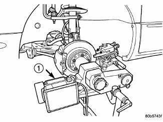
Fig. 161: On-Car Brake Lathe
- - ON-CAR BRAKE LATHE
If the rotor surface is deeply scored or warped, or there is a complaint of brake roughness or brake pedal pulsation, the rotor should be refaced using a hub-mounted on-car brake lathe (1), or replaced.
The use of a hub-mounted on-car brake lathe (1) is highly recommended to eliminate the possibility of excessive runout. It trues the brake rotor to the vehicle's hub and bearing.

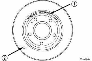
Fig. 162: Minimum Brake Rotor Thickness (Typical)
- - ROTOR MINIMUM THICKNESS MARKING
- - ROTOR
NOTE: All brake rotors (2) have markings for minimum allowable thickness cast on an unmachined surface of the rotor (1) or stamped into the hat section.
Minimum allowable thickness is the minimum thickness which the brake rotor machined surface may be cut to.
CAUTION: Do not machine the rotor if it will cause the rotor to fall below minimum thickness.
Before lathe installation, verify the brake rotor face and the hub adapters are free of any chips, rust, or contamination.
When mounting and using the brake lathe, strict attention to the brake lathe manufacturer's operating instructions is required.
Machine both sides of the brake rotor at the same time. Cutting both sides at the same time minimizes the possibility of a tapered or uneven cut.
When refacing a rotor, the required TIR (Total Indicator Reading) and thickness variation limits MUST BE MAINTAINED. Extreme care in the operation of rotor turning equipment is required.
 Diagnosis and Testing
BRAKE ROTOR
Any servicing of the rotor requires extreme care to maintain the rotor within
service tolerances to ensure proper
brake action.
Excessive runout or wobble in a rotor can increase pe ...
 Removal
FRONT
1. Raise and support the vehicle.
Fig. 163: TIRE AND WHEEL MOUNTING
2. Remove the wheel mounting nuts (3), then the tire and wheel assembly (1).
NOTE: In some cases, it may be necessary ...
See also:
Description, Operation
DESCRIPTION
The battery cables are large gauge, stranded copper wires sheathed within a
heavy plastic or synthetic rubber
insulating jacket. The wire used in the battery cables combines excellent ...
Installation
CAUTION: Be certain to adjust the refrigerant oil level when
servicing the A/C
refrigerant system. Failure to properly adjust the refrigerant
oil level will prevent the A/C system fro ...
Adjustments
NOTE: Perform all differential bearing preload measurements with the
transfer shaft
and gear removed.
DIFFERENTIAL BEARING PRELOAD ADJUSTMENT USING EXISTING SHIM
Fig. 348: Installing Too ...
