Dodge Journey: Installation
NOTE: Perform 1 through 5 on each side of the vehicle to complete pad set installation, then proceed to 6.
NOTE: Make sure that the audible wear indicator (if equipped) is placed toward the top when the inboard brake pad is installed on each side of the vehicle.
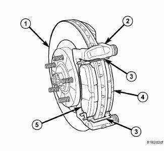
Fig. 121: FRONT BRAKE PADS
NOTE: If the brake pads have a protective paper on the rear face of the brake pad plate, it must be removed before pad installation.
1. Place the brake pads (4, 5) in the abutment shims (3) clipped into the disc brake caliper adapter bracket (2) as shown. Place the pad with the wear indicator (if equipped) attached on the inboard side (2).
2. Completely retract the caliper piston back into the bore of the caliper. Fig. 122:
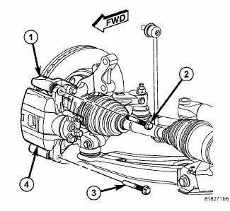
Fig. 122: CALIPER GUIDE PIN BOLTS
CAUTION: Use care when installing the caliper (4) onto the adapter bracket (1) to avoid damaging the boots.
3. Install the disc brake caliper over the brake pads on the brake caliper adapter bracket.
CAUTION: When removing or installing a caliper guide pin bolt, it is necessary to hold the guide pin stationary while turning the bolt. Hold the guide pin stationary using a wrench placed upon the pin's hex-shaped head.
4. Align the caliper guide pin bolt holes with the adapter bracket. Install the upper (2) and lower (3) caliper guide pin bolts. Tighten the guide pin bolts to 35 N.m (26 ft. lbs.).
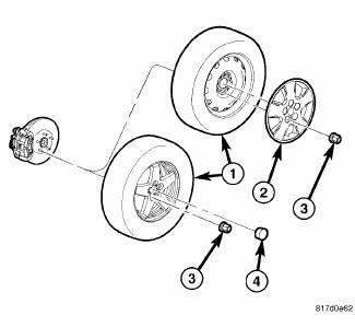
Fig. 123: TIRE AND WHEEL MOUNTING
5. Install tire and wheel assembly (1). Install and tighten wheel mounting nuts (3) to 135 N.m (100 ft. lbs.).
6. Lower the vehicle.
7. Pump the brake pedal several times before moving the vehicle to set the pads to the brake rotor.
8. Check and adjust the brake fluid level in the reservoir as necessary.
9. Road test the vehicle and make several stops to wear off any foreign material on the brakes and to seat the brake pads.
 Removal
1. Raise and support the vehicle.
NOTE: Perform 2 through 5 on each side of the vehicle to complete pad
set
removal.
Fig. 117: TIRE AND WHEEL MOUNTING
2. Remove the wheel mounting nuts ...

See also:
Installation
Fig. 51: Front Hub And Bearing Mounting
1. If required, install the hub and bearing (1) by sliding it into the
knuckle.
2. If installing hub and bearing, install the four bolts (2) fastening t ...
Operation
FIXED DISPLACEMENT A/C COMPRESSOR
The Denso 10SR15 and 10SR17 fixed displacement A/C compressors are driven by
the engine through an
electric clutch, drive pulley and belt arrangement. These A/C c ...
Installation
BATTERY HARNESS
Fig. 36: Mounting Clips And TIPM Housing
1. Position the battery harness into the vehicle.
2. One at a time, install the battery harness retaining pushpins, fasteners and
rout ...
